Theoretical Background
This is a brief introduction to the theoretical background of faser. For a more detailed explanation, please refer to the original publications.
Light Distribution in the Focal Region
In optical imaging systems with a high numerical aperture (NA
During the 1950s, Richards and Wolf introduced a detailed mathematical framework to describe the electromagnetic (EM) field distribution in the focal region of a high NA objective lens 2 3. The validity of this integral representation has been rigorously examined in subsequent studies 4 5. The main assumptions underlying this theory are as follows:
- The beam exiting the pupil has a spherical wavefront with a radius equal to the objective’s focal length,
. - Each diffracted ray is modeled as a plane wave propagating toward the lens’s geometrical focal point, represented by the wave vector
. - The observation point is significantly distant from the exit pupil (
, see Fig. 1a), and the pupil diameter is much larger than the wavelength ( ).
This framework, known as vectorial diffraction theory, expresses the electric field
Here,
Using the geometry shown in Fig. 1, the diffraction integral is given by:
In this expression,
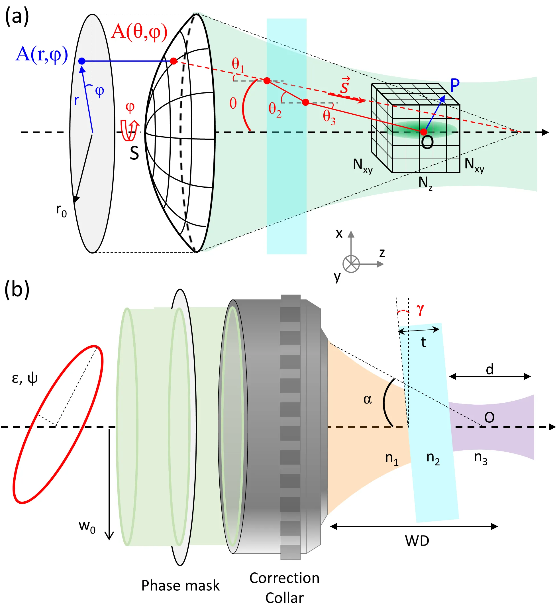
Figure 1. Schematic of the geometry used for simulations:
- (a) In vectorial diffraction theory, the incident pupil field
is transformed into a spherical wavefront by the objective lens, which then propagates to the focal point. The intensity at any point near the focus is computed, considering propagation through stratified media (e.g., immersion liquid, coverslip, and sample). - (b) Beam properties, including ellipticity, intensity profiles, and potential aberrations, are characterized before the objective lens. A phase mask can also be introduced, particularly for beam shaping in applications like STED microscopy.
Footnotes
-
Gu, M. (2000). Advanced optical imaging theory. Springer Science. ↩ ↩2
-
Richards, B. (1959). “Electromagnetic diffraction in optical systems, I. An integral representation of the image field.” Proceedings of the Royal Society A. ↩
-
Wolf, E. (1959). “Electromagnetic diffraction in optical systems, II. Structure of the image field in an aplanatic system” Proceedings of the Royal Society A. ↩ ↩2
-
Foreman, M. R., & et al. (2011). Computational methods in vectorial imaging Journal of Modern Optics. ↩
-
Leutenegger, M. (2006). Fast focus field calculations Optics Express. ↩
-
Török, P., & et al. (1995). Electromagnetic diffraction of light focused through a planar interface between materials of mismatched refractive indices: an integral representation Optical Society of America ↩